Connecting the Portenta Vision Shield to TTN Using LoRa®
This tutorial explains how to connect your Portenta H7 to The Things Network (TTN) using the the Portenta Vision Shield's LoRa® Connectivity feature.
Overview
This tutorial explains how to connect your Portenta H7 to The Things Network (TTN) using the the Portenta Vision Shield's LoRa® Connectivity feature. A data communication channel will be enabled between the H7 and a TTN application that will be configured on your TTN console.
In order to connect your Portenta to the TTN, make sure you are within the range (max. 10 Km) from an available LoRa® Gateway. Indoor gateways will have a much shorter range. It is recommended that you check LoRa® Gateway availability on The Things Network map before you try this tutorial.
Goals
- About LoRaWAN® and The Things Network,
- About creating a TTN application,
- How to establish a connection between the Portenta H7 and the TTN.
Required Hardware and Software
- Portenta H7
- Portenta Vision Shield - LoRa
- 1x Dipole Pentaband antenna or a UFL Antenna of the H7
- Arduino offline IDE or Arduino Web Editor
- USB-C® cable (either USB-A to USB-C® or USB-C® to USB-C®)
- An account with The Things Network
Updating the LoRa® Module Firmware
To be able to use the LoRa® functionality, we need to first update the firmware on the LoRa® modem. This can be done through Arduino IDE by running a sketch included in the examples from the MKRWAN library.
Connect the Portenta H7 and the Portenta Vision Shield - LoRa to your computer and open the Arduino IDE.
Install/update the MKRWAN library from Arduino IDE menu Tools > Manage Libraries. Type "MKRWAN" to find the library and click 'Install' or 'Update' if necessary. This library provides all the APIs to communicate with LoRa® and LoRaWAN® networks.
Open the MKRWANFWUpdate_standalone sketch from the Arduino IDE menu: File > Examples > MKRWAN.
Upload the sketch.

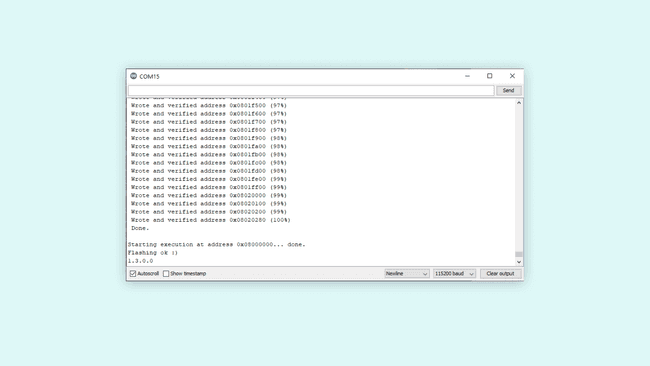
- Open the Serial Monitor and wait for the update to be confirmed.
Connecting to the TTN
The Portenta Vision Shield - LoRa can be connected to the TTN and can transmit data to other devices connected to this network through a secure channel. This channel is nothing but an application on the TTN network dedicated for your board. In this tutorial, you will be guided through a step-by-step process of setting up your Portenta board and the Vision Shield - LoRa to communicate with a TTN application. As stated before, to be able to follow this guide, you need to be under coverage of one of the TTN gateways. You can check for the coverage now if you have not done so yet.
1. Setting up the Environment
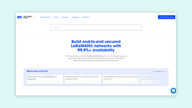
Start by going here. First choose your region. Next, sign in with your The Things Network account. If you do not have an account, create a new one on the login page. Then fill all the required fields to complete a new registration.
2. Creating an App on TTN
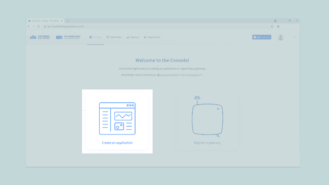
Once you have created an account with TTN, you need to create a TTN application. An application provides a way to aggregate data from different devices, and then use these data with other 3rd party integrations. After signing in, click on Create an application, or Go to applications if you already have created one.
Here you will have a list of all your applications. Now create your first app by pressing the Create an application button.
You have now to fill only the first two fields:
- The first one is the Owner of your app, it will automatically have you as the owner.
- The second one is the ID of your app: this must be lowercase and without spaces.
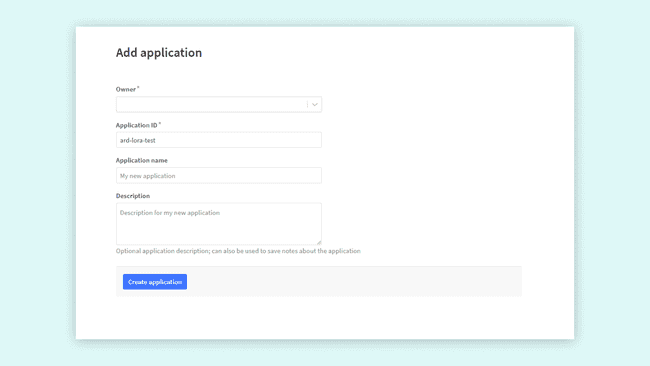
After completing these two fields, press the "Create application" button located at the bottom left corner of the page. The dashboard will then show you an overview of the newly created app.
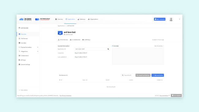
Let's take a closer look at these sections:
- Application Overview: in order to use this app, you will need the Application ID and a device specific AppKey. An EUI is a globally unique identifier for networks, gateways applications and devices. The EUIs are used to identify all parts of the LoRaWAN® inside the backend server.
- End devices: here you can see and manage all the associated devices (e.g. your Portenta H7 with Portenta Vision Shield - LoRa, Arduino MKR WAN 1300 or MKR WAN 1310), or proceed with the registration of a new one. Registering a new device lets you generate an AppEUI and an AppKey.
- Collaborators: here you can see and manage all the app collaborators, to integrate with other collaborative platforms or to manage access rights to the app with other TTN registered profiles.
- API keys: here you can create an API key, it is the most sensible information. It is basically the key to gain access to your app, so keep it safe.
3. Configuring the Portenta Vision Shield
It iss now time to connect your Portenta H7 and Portenta Vision Shield - LoRa to TTN. You will need to upload code to the board, so, as you probably already know, there are two options:
- Use the Arduino Web Editor
- Use the Arduino IDE, (this is the option this guide will follow)
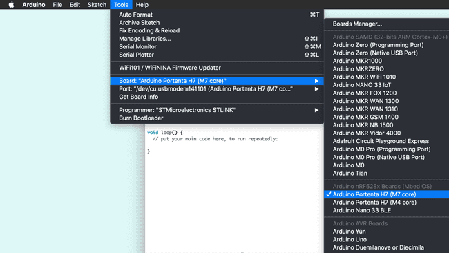
Plug the Portenta Vision Shield - LoRa to the Portenta H7 and them to your PC through the USB port. Be sure to have selected the right board "Arduino Portenta H7 (M7 core)" and the right port.
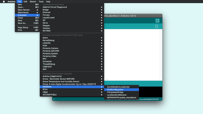
The LoRa® module on the Portenta Vision Shield - LoRa can be accessed by using the MKRWAN library(if you cannot find it in your examples list, you can go to Tools > Library Manager and type "MKRWAN library" to install it). This library provides all the APIS to communicate with LoRa® and LoRaWAN® networks and can be installed from the library Manager. The first code you need to upload and run is from the MKRWAN library, and its name is FirstConfiguration.
The only line you may need to change before uploading the code is the one that sets the frequency. Set the frequency code according to your country if needed. You can find more information about frequency by country at this TTN link.
1// change this to your regional band (eg. US915, AS923, ...)2 if (!modem.begin(EU868)) { ...Consider that in Australia the boards connect correctly to TTN gateways on AS923 frequencies; AU915 frequencies requires the selection of sub band 2, not yet implemented in the firmware.
Once you have added to the sketch the frequency according to your country, you can upload it to the board. Then, when the upload is completed, open the Serial Monitor. The following details will show up:
1Your module version is: ARD-078 1.2.12Your device EUI is: a8xxxxxxxxxxxxxx3Are you connecting via OTAA (1) or ABP (2)?In order to select the way in which the board is going to connect with TTN (OTAA or ABP), you need to configure it on the TTN portal. You will see which option you should select in the following steps.
4. Registering the Portenta on TTN
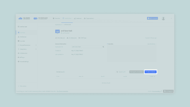
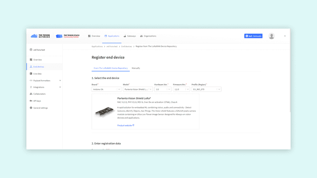
Before your Portenta H7 can start communicating with the TTN, you need to register the board with an application. Go back to the TTN portal and scroll to End devices section on your Application dashboard, then click Add end device.
On the registration page, first you have to fill in information about your board. Select brand Arduino SA, and Portenta Vision Shield - LoRa as the model. Hardware and firmware versions will automatically be set to the newest ones. Then set your preferred region.
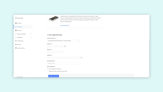
In the second step of registering the device, fill in End device ID and DevEUI. You can click the generate button next to the AppKey field to generate an app key for this device. Similarly, you can press the button next to the AppEUI field to make it all zeros, or enter your own AppEUI.
Note: The Device ID must be lowercase and without spaces. The DevEUI should be copied from the Serial Monitor.
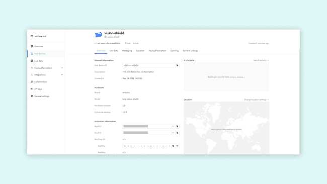
After pressing the Register button, your board will show up on the Device Overview page. You can now see all the information needed to complete the Arduino setup.
5. Connecting to TTN
Once your board has been registered you can send information to TTN. Let's come back to the Serial Monitor and proceed. It will ask for:
- Activation mode (that, in this case, is OTAA),
- The Application EUI
- The App Key.
Lets start by making a connection Over-The-Air (OTA). Enter "1" in the Serial Monitor input box and press ENTER. Then, find the EUI and the App key from TTN Device Overview page. You can read more into OTA vs ABP activation mode here.
1Your module version is: ARD-078 1.1.92Your device EUI is: a8xxxxxxxxxxxx0a3Are you connecting via OTAA (1) or ABP (2)?4Enter your APP EUI5Enter your APP KEYNext, introduce the APP EUI and the APP KEY in the Serial Monitor. If this process is done successfully, you will see this message:
1Message sent correctly!Conclusion
If you receive this message, you have managed to configure the Portenta H7 and the Portenta Vision Shield - LoRa on TTN.
You have retrieved the device EUI, used it to register the device in the TTN console, and programmed the board using the data provided by TTN. Now, you can send data over the LoRa® network which can be viewed from anywhere in the world (as long as we have an Internet connection and your device is in the range of a TTN gateway).
Next Steps
- Try sending uplink and downlink messages between Portenta and your TTN application with LoraSendAndReceive sketch from the MKRWAN library.
- Experiment your board's capabilities with OpenMV and the examples from the dedicated library for Arduino. You can continue with this tutorial from the Arduino Documentation site.
- Combine LoRaWAN® protocol with an OpenMV example to develop your own IoT application. Take advantage of the board's camera to detect, filter, classify images, read QR codes or more.
Troubleshooting
The most common issue is that the device cannot connect to a TTN gateway. Again, it is a good idea to check if you have coverage in the area you are conducting this tutorial, by checking out this map.
If you are within good range of a gateway, you should also try to move your device and antenna to a window, and even hold it out the window and move it around. This has proven successful on numerous accounts, as the signal can travel less obstructed.
Suggest changes
The content on docs.arduino.cc is facilitated through a public GitHub repository. If you see anything wrong, you can edit this page here.
License
The Arduino documentation is licensed under the Creative Commons Attribution-Share Alike 4.0 license.